
First Computer System
 The first computer I put in was an old Pentium system I had sitting around. Specs:
- Compaq Pentium 166MMX with onboard video
- 64MB of RAM
- SBLive soundcard
- 2x CD-ROM
- 17″ monitor
Not a powerhorse by any means, but it sure does play a mean game of Punch-Out, and handled all of the true retro games with easy. However, after playing a few newer games on this system, I realized that I will DEFINITELY need to buy an updated PC to make this arcade machine really rock.
Final Computer System
 The slower computer was eventually replaced by a hack-a-pc I put together using an old Dell case with a replaced motherboard and cpu. While it doesn’t look like much on paper, for the time I built it (2001) it was more than enough for emulation Specs:
- Duron 1.2Ghz processor
- 256mb of RAM
- OEM-ATI Raedon 7500 card with TV output.
- Sony 27″ CRT TV (This thing weighs a TON!)
Getting the TV output to work correctly took a little bit of tweaking, but it looks great. The system is capable of playing all games including all of the latest NeoGeo games, at full speed. This is MUCH better than the P166. ;)
The only problem that I ran into was that the new motherboard was not compatible with the older Dell powerswitch. The first PC was nice because it used ATX motherboard. I simply left the hard power switch in the ON position and let the power strip turn on everything at once. Until I have a permanent solution to this dilemma, I simply ran the “power” pins from the motherboard to an extra Happ button. To turn on the PC I simply click the button. Not ideal, and not very pretty, but it works.
Painting
I didn’t know what would happen if I just painted, so I decided to put a coat of latex primer on everything. I didn’t want to have to re-paint everything if the black paint started to fade or bleed. here is a picture of the control panel with a coat of the white primer.
HORAY! The cabinet looks GREAT with the black paint, doesn’t it? It turned out better than I had imagined. I just brushed it on. I did take care to be sure that all of the brush strokes were all going the same way. Piece of cake! There’s no need to paint any of the edges since the 3/4″ T-Molding will eventually be glued onto the edge.

mame-paint-cp
The control panel with a latex primer

mame-paint-cabinetfront
First coat of black paint on the cabinet

mame-paint-cabinetback
Letting the back door dry.

mame-final-09-01-01
The cabinet and control panel painted
Audio System
 I bought a speaker/subwoofer combo at the local Fry’s Electronics for only $14.99!! Funny thing is that when I was comparing the sound quality in the store, these speakers sounded the best. They just happen to cost the least. BONUS!
I had them apart in no time. The actual speakers are pretty small, but they should work fine for starters. I’m planning on mounting the power/volume board in the cabinet below the control panel. It looks like I’ll have to get a soldering iron!
Update: Borrowed a soldering iron from a buddy and got everything disconnected so I could remove the speaker enclosures from the speakers. I left the sub-woofer intact. I then soldered some of the “bell” wire I got for the control panel wiring and made some longer speaker cables.
 Here is a picture from above the cabinet looking down. I temporarily removed the top panel so I could take this picture. You can see the 2 speakers on each side mounted over the speaker openings. I put down two pieces of black craft felt in between the speaker and the wood so that the light wouldn’t leak through the speaker grill.
I took the subwoofer and screwed it directly between the two main speakers. I figured that this is would be the best place to get the most sound out of the subwoofer to the players ears.
The final challenge was where to put the on/off and volume controls. Since the whole system was on a power strip, I planned on leaving the sound on all the time, but having access to the volume control was important. I was able to reuse part of the plastic casing from one of the speakers to make this look half-presentable.

T-Molding Installation
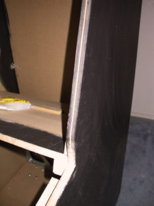 I used a 1/8″ rabbet bit on my router to route for the 3/4″ t-molding. Word of advice: Route for t-molding BEFORE you paint. I put a few scratches in the finish paint job while I was routing. I didn’t think about it before, but now it makes sense. In any case, here is a picture of what the routed edge should look like before the molding is installed.
Here is a drawing of what the bit looks like. Once you put it on your router, you actually set the shaft-depth and then tighten it up so that the bit is at the right depth to be exactly in the middle of the wood. The yellow circle-part of the bit is the part that digs into the wood and with the guide, it cuts an exact depth all the way around. I actually turned my cabinet on its side, then put the router down flat on the side of the cabinet and routed around the edge. You don’t have to think twice about keeping a straight line at all since the router is already locked into place to cut exactly in the center of the edge and the guide keeps the cutting depth just right.

I ordered 40 feet of t-molding from t-molding.com. You’d think that 40 feet is way too much, but I used all but 3 feet of it.
 Using a hot-glue gun I installed the molding. I usually put down about 6-8″ of glue at a time and then held the t-molding in place for about 1 minute. Be sure not to do a long strip AND a corner at the same time, it’s harder to hold. Take your time, this is a detail that will make your cabinet look GREAT if done well. The angles that defy gravity… are hard. If you have the patience, you can put your cabinet on it’s back while gluing these angles to keep the hot glue from dripping on your final paint job.
On a side note, I bought a 24-pack of glue sticks for the project. I was thinking that would be WAY too much glue, but it turned out that I used ALL but 1 stick. Keep that in mind and it may save you an unexpected trip to Home Depot. :)
Marquee
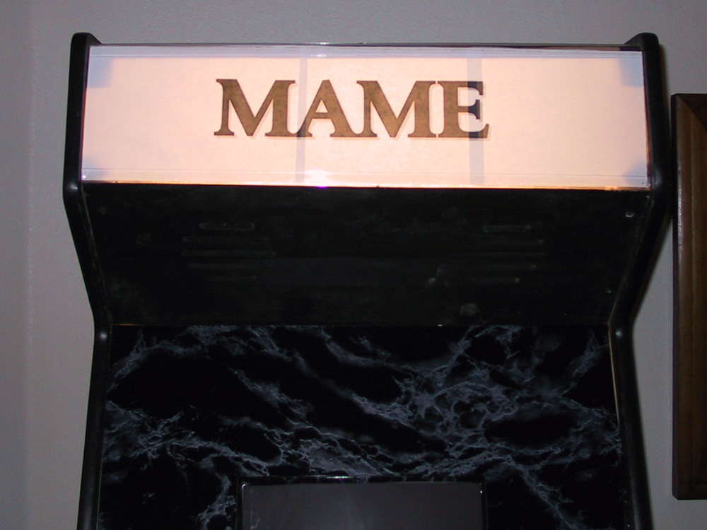 Yeah yeah.. I was so excited to see what the cabinet would look like, I had to make up a temporary marquee. Really boring, I know. but doing this temporary marquee taught me a few things. First, although you can’t see it plainly from the picture, apparently I made a minor error during measuring. The marquee area is actually 1/2″ larger on one side than the other. This became obvious when I measured to cut the plexiglass, and was important when I designed the finished logo in Photoshop.
I noticed while looking at the corners of the temporary marquee, you can clearly see the 2×2 supports silhouetted. I knew that when I design the final marquee, I’ll need to be sure I don’t put any important graphic elements in these areas.
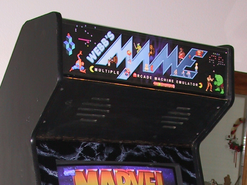 Well, after a few hours in Photoshop I was able to finish my marquee. The final piece is 28″ by 7.5″ at 150dpi. (4200px by 1125px) I had it printed up at the local Kinkos for around $16. Although the plexiglass in this picture is making it appear glossier than it should, the Kinkos print out was superb. The black ink they used was truly flat BLACK and turned out great. You’ll notice that I didn’t put anything above Qbert or below Spiderman… to avoid the lack of light behind those areas. This picture also shows the bottom retaining plastic clear angle molding better than any of the other pictures.
Here it is, in its final glory. :)

Here’s a quick rundown on how I made it: There are a bunch of places that have the logo, but I eventually found the original creators of the main MAME logo that I used, and it is on OscarControls’ Website (Website no longer active, sorry) To capture each character I played that particular game in MAME and did the old alt-print-screen combo to capture a screenshot. I pasted it as a new layer, did some transform-scale so that each character would be large enough to see, and then cleaned up the edges. The I went through my huge collection of fonts to find just the right combination for the “Webb’s” portion, and added a few effects to make it match the style of the MAME logo. After a little bit of shuffling around, I wound up with my marquee. That is about it. Pretty simple.
Download the Marquee
After MANY requests, I have finally decided to post the Photoshop source file for my marquee. The file is a 6.8MB ZIP file, and contains a Photoshop 7.0 file and the font I used for my name.
BEFORE YOU DOWNLOAD: All I ask, is if you download and use this marquee as a starting point for your own marquee, and you post pictures of your cabinet online, that you give Oscar Control and myself credit, and post a link back to this page on my website. I just want to be sure everyone gets credit where credit is due. Enjoy!!!
 Monitor Bezel
 Monitor Bezel
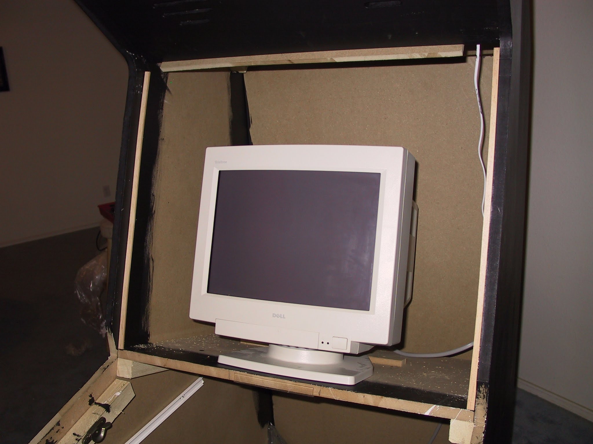
Before I installed the final 27″ TV screen, I made use of an extra 17″ PC monitor. The design for the bezel needed to be able to accommodate the smaller monitor now, and easily be updated to a larger one later. Contact paper was the solution. A quick test to ensure the contact paper could be easily removed from the plexi glass later proved it. So, I can install it now, and take it off later, resize, and re-install! WHOO hoo!
Plexiglass
So, first order of business is to get the plexiglass. I got one sheet of 30″x36″ lexan. I figured I could cut the 30″ inch side down to the width of the opening, 28″, and the length I could cut into 3 pieces: a 24″ monitor section, and 2x 7″ marquee pieces. I cut the plexiglass with a fine-tooth plywood blade on my circular saw. There was a little bit of chipping around the cut edge, but not much.
Next step was to put the contact paper on. But, before I could do that, I needed to install the plexiglass and mark where the current monitor would line up.
 I decided to install 1/2″ quarter-round molding surrounding the area where the molding would be to act as back-support. In this picture you can see what the molding looks like installed from behind. I was thinking about installing some 2×2 supports like I used in the cabinet construction, but after a quick measurement of my 27″ TV I have in the bedroom, there wouldn’t be enough room width-wise when I go to install it later. So, 1/2″ molding worked perfectly. One small tip: Clamp them and pre-drill the holes. If you simply try to power-drill the screws in, the MDF will create a little “hill” of wood where the screw enters and keep the molding from holding tight to the MDF.
First I aligned the molding so it was flush with the front on the monitor support shelf. Then I just followed the molding up the inside of the monitor area keeping the same distance from the edge as I went.
After a test-installation I realized I had two challenges: I needed to support behind the plexiglass at the top, and I needed something to hold the plexiglass from the bottom.
Solution to challenge #1: A scrap piece of 1/2″ MDF that I was able to attach across the top. Drilling a drywall screw into the EDGE of the speaker panel was scary business, so pre-drilling was definitely in order.
 Solution to challenge #2: To support the bezel at the front edge I decided to install a standard clear plastic “edge saver” strip. This is the same stuff you install on the corner of an interior wall to keep it from getting banged up. I cut a small piece that would not get in the way when the control panel was finally installed. If the plastic strip doesn’t work out, I’ll just replace it with a more-sturdy metal angle bracket later.

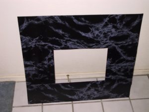
mame-bezel-plexi
The plexi bezel with shelf paper applied

mame-bezel-molding
Quarter-round molding seen from inside the cabinet

mame-bezel-holder
Holding the bottom edge of the bezel.
mame-bezel-noplexi
Before bezel is installed

mame-bezel-installed
After bezel is installed

mame-final-09-23-01
Final cabinet with 17″ monitor bezel
Coin Door
 A friend referred me to someone who had an Happ coin door for sale. It was several years old but it was never used, and still in the original packaging from Happ. For $35 I couldn’t resist. For me, a coin door on the front really helps make the cabinet look authentic!
Since the part was so old, I didn’t know if there were any measurements available, so I just measured the actual part. I measured the front door and measured the correct size in order to mount the coin door exactly centered. I used a t-square to be sure that the hole was exactly straight to the top and sides. The tricky part was trying to get the curves right. Basically I just eye-balled them and they worked out just fine.
Attaching the door to the front door was pretty easy. There are 5 “fingers” that come out from the back of the coin door. These fingers can be used to mount the door on 1/2″ or 3/4″ plywood, in my case 1/2″. The screws hold the fingers tight to the wood and presto!
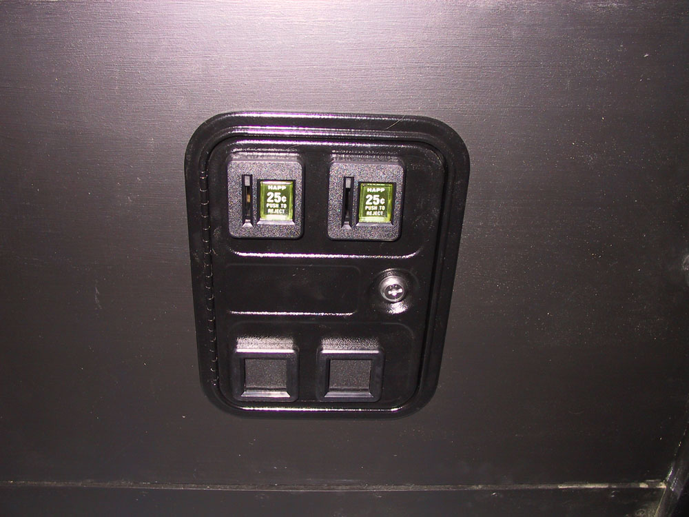 Looking at the final installation, it looks pretty authentic to me. The only thing I would consider doing last would be to wire the lights for the coin slots and replace the “Happ Controls” sign on the coin release button. We’ll see.
Other MAME Articles in this Series

My MAME Arcade Machine
You Built a WHAT?? Many years ago (early 2000's), I built a MAME arcade machine cabinet. It was an incredibly fun and challenging project, and the final machine was so much fun to play. Even today, I have an occasional conversation where I bring it up,...

MAME – Design and Plans
Any time I start a new project, I always love going out and doing research. A huge win was discovering the Build Your Own Arcade Controls website, dedicated to people who had already built MAME cabinets, and resources with how to find anything you need to...

MAME – Cabinet Cutting
Measuring it Out First step was to get the wood. I got 2 pieces of 3/4" MDF 4x8' which would be used mostly for the sides of the cabinet, the floorboards, and other parts that needed thicker support. MDF is "Medium Density Fiberboard" which is one grade higher than...
MAME – Cabinet Assembly
First order of business was to measure out and mark where all of the 2x2 supports would be attached. I figured that the kickboard was 3" and the casters I got should be mounted 2 1/4" recessed. So I measured in 2 1/4" and clamped in the first 2x2 support. This was...

MAME – Control Panel
The control panel is one of the core aesthetic reasons I decided to make a cabinet. The control panel is your physical interface to the games; the joysticks, trackball and buttons. My design for the control panel was so that it could be easily removed and...